SYST 210
System Design
Kathryn Blackmond Laskey
Department of Systems Engineering and Operations Research
George Mason University
Homework Assignment 4: CORE Exercise
Due September 22, 2020, noon
Reading assignment: Chapter 3, 6.1-6.4
In this assignment, you will create a CORE model containing
mission requirements and an external systems diagram for the
UChekIt self-checkout system. Your final submission must be
neat and readable. Every page must include your name, the
assignment number, and the due date. Please upload your assignment
to Blackboard by the due date and time.
This assignment uses the CORE software. CORE is installed in
the VSE Lab in ENGR 1506. You can also install CORE on your home
computer. Instructions for installing CORE can be found in the
MBSE Software folder on Blackboard. Install the CORE software on
your computer as described in the installation instructions. Open
CORE. Click "Model Assistant" in the Project pane and uncheck
"Auto-create Root Functions." (This will prevent CORE from creating
a performing function whenever it creates a component. We don't want
to auto-create because we are going to create functions and
components manually.) Also uncheck "Auto allocate on Decomposition",
"Auto relate on allocation,"and "Auto-create root states." After you
have become practiced in CORE, you may find auto-create
assistance useful, but when we are just getting started we will do
these things manually.
We will work together on this
assignment in class and you will complete it for homework. If you need help
with some of the steps, you can refer to the CORE tutorial on
Blackboard, which walks you through the
same steps in detail on a different system.
- Save the UChekIt
Source Document on your local system, select the element
extractor from the Tools menu, and load the source document
into CORE. You will need to select "html" as the file type in
the dialog box to open the file. Define a document called
"UChekIt Source Document," and number it Doc.1. Select
"Project Memo" as the document type. In the
"Description" field, copy the text of Section 1.0. Use
Extractor > Create Element to make a CORE element for the
document.
- Define a requirement MR.0 with name "Mission
Requirements." For the description field, import the first
sentence in Section 3.0 of the UChekIt Source Document.
Define six mission requirements MR.1 through MR.6
corresponding to the six numbered mission requirements in
the source document. Categorize them as originating
requirements. Set the type of the first requirement to
"composite;" the second and third to "perforamance;" the
fourth requirement to "nil" (none of the listed types
applies to this requirement); the fifth to "functional; and
the sixth to "composite." Use the "refines" and "refined by"
relation to make sure they are organized hierarchically in
CORE with MR.1 through MR.5 refining MR.0. Link MR.0 to the
source document via the "documented by" relation.
- Define a function F.0, "Provide Self-Checkout Services" in
CORE to represent the top-level function for
UChekIt. Create functions for the external systems
and the supersystem as described in the UChekIt Function Table.
Describe the functions in the "description" field.
- Trace the top-level function to your top-level mission
requirement using the "based on" and "basis of" relations.
- Add items for each of the inputs, outputs and controls listed
in the UChekIt
Function Table. Connect these items to the functions
using the "input," "output" and "trigger" relations in CORE. Use
the "decomposed by" relation to decompose the item "messages to
customer" into "checkout opportunity" and "payment result
message."
- Define components SYS.1 for the main system, ESYS.1 through
ESYS.4 for the external systems, and CSYS.0 for the system
context. Enter descriptions for the components. Use the
"built from" relation to connect the context to UChekIt and the
external systems. Connect these components to their functions
using the "allocated to" relation. These components should
correspond to the mechanisms in the UChekIt Function Table.
Trace SYS.1 to MR.0 using the "specified by" relation.
- Run the "table maker" script by choosing "Run Script" from the
Tools menu and choosing TableMaker from the drop-down
menu. Select "Requirements" as the segment. Select
attributes Number&Name, Description, Type, Origin, and Basis
of. Select "Numeric" for the sort block.
- Run the table maker script for components, selecting
Number&Name, Description, built from, built in, and
performs.
Do the same for functions, selecting Number&Name,
Description, inputs, triggered by, outputs, allocated to, and
based on.
- Select the source document and create a requirements
diagram. Use a note to put your name on the diagram. Save
your diagram as a PNG file.
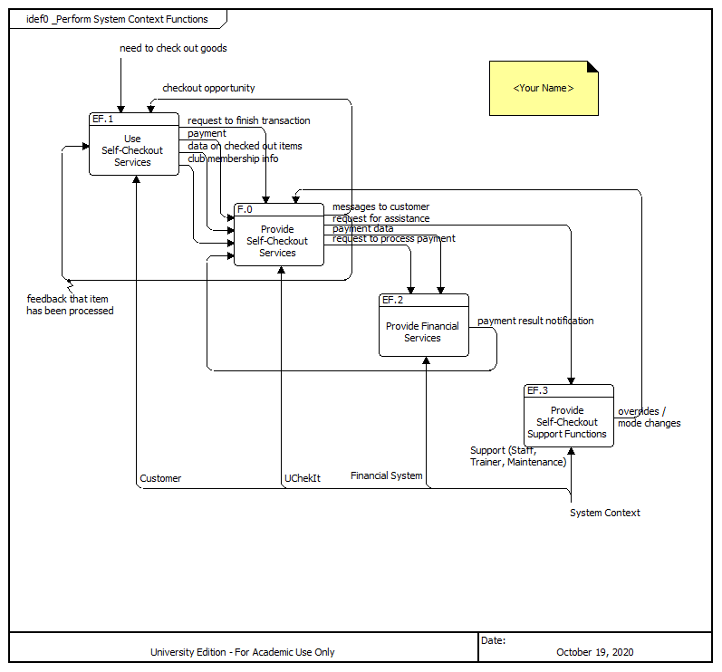
- Select the Supersystem function and create an IDEF0 diagram. This is the
UChekIt external system diagram). Use a note to put your
name on the diagram. Save your diagram as a PNG file. If your functions are
not in the same order as shown in the example, you can reorder
them by selecting the function, right-clicking, and selecting
Presentation / Change node order. (The CORE default background
for all diagrams is blue. You may use the default or change if
you prefer by right-clicking the diagram, selecting View >
Local diagram options > Fill. Background color is a matter
of preference and will not affect your grade.)
- Combine the tables you created in Parts 7 and 8, and the
diagrams you created in Parts 9 and 10 into a report. Put each
table or diagram on its own page, with an appropriate title at
the top of the page. Make a cover page with the title: "UChekIt
CORE Lab," your name, and the date. Make sure your name, the
assignment number, and the date appear on every page. You can do
this in MS Word using headers and footers. Upload your
report to Blackboard. You will be graded on the report you turn
in. You do not have to submit your CORE model.
SYST 210 homepage